The starting point is to establish truth tables for the 8 logic symbols:
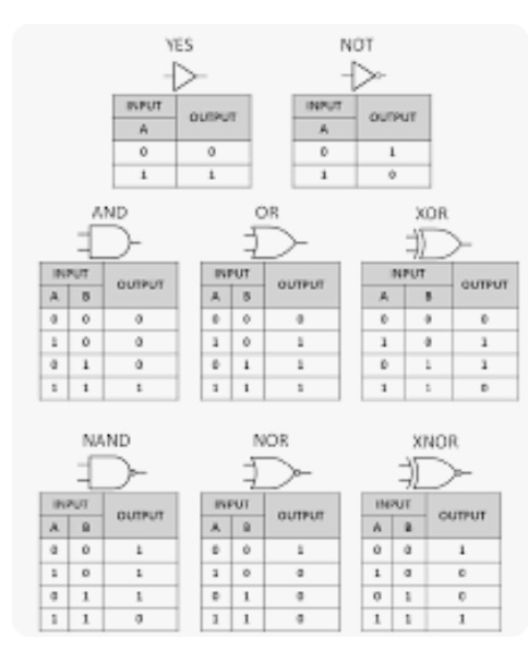
These can now be applied to the circuits.
| A |
B |
C |
D |
W |
X |
Y |
Z |
Q |
| 0 |
0 |
0 |
0 |
0 |
1 |
0 |
0 |
1 |
| 0 |
0 |
0 |
1 |
0 |
0 |
0 |
0 |
0 |
| 0 |
0 |
1 |
0 |
1 |
1 |
0 |
1 |
1 |
| 0 |
0 |
1 |
1 |
0 |
0 |
0 |
0 |
0 |
| 0 |
1 |
0 |
0 |
0 |
1 |
0 |
0 |
1 |
| 0 |
1 |
0 |
1 |
1 |
0 |
1 |
0 |
1 |
| 0 |
1 |
1 |
0 |
1 |
1 |
0 |
1 |
1 |
| 0 |
1 |
1 |
1 |
1 |
0 |
1 |
0 |
1 |
| 1 |
0 |
0 |
0 |
0 |
1 |
0 |
0 |
1 |
| 1 |
0 |
0 |
1 |
0 |
0 |
0 |
0 |
0 |
| 1 |
0 |
1 |
0 |
1 |
0 |
0 |
1 |
1 |
| 1 |
0 |
1 |
1 |
0 |
0 |
0 |
0 |
0 |
| 1 |
1 |
0 |
0 |
0 |
0 |
0 |
0 |
0 |
| 1 |
1 |
0 |
1 |
1 |
0 |
1 |
0 |
1 |
| 1 |
1 |
1 |
0 |
1 |
0 |
0 |
1 |
1 |
| 1 |
1 |
1 |
1 |
1 |
0 |
1 |
0 |
1 |
Although this is the main results table, we may require to work out intermediate results by examining the circuit more closely.
From the circuit diagram X=A̅.D̅, Y=D.B, Z=D̅.C; W=Y+Z.
These logical expressions can also be written:
X=NOT-A AND NOT-D, Y=D AND B, Z=NOT-D AND C; W=Y OR Z; Q=X OR W; or
X=¬A∧¬D, Y=D∧B, Z=¬D∧C; W=Y∨Z; Q=X∨W.
Q=(¬A∧¬D)∨((D∧B)∨(¬D∧C)) is the combined Boolean expression.
From this, whenever A=D=0 are zero, X=1 and all other values of X are 0. So take the main table and fill in X. Also, whenever B=D=1, Y=1 and all other values of Y are 0; whenever D=0 and C=1, Z=1, otherwise Z=0. Finally, find Q and complete the table. (1=signal/current, 0=no signal/current.)
When completed the main table shows by Q=1 when there is an output for all 16 possible values of A, B, C, D, from no inputs to all inputs.
